


Projen Taiwan - Auto Tools, Hand Tools manufacturer
CAW0040 TAIWAN CALIBRE Lambda Tester and Simulator
CAW0040 TAIWAN CALIBRE Lambda Tester and Simulator
Lambda tester
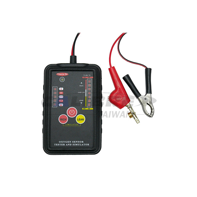
Lambda tester simulates and tests 1V Zirconia and 1V/5V Titania oxygen sensors to check ECU function and identify wire types. Powered by a single 9V (6F22) battery.
Manual Download Here
Feature:
- This device is designed to test and to Simulate 1V Zirconia and 1V/5V Titania type oxygen Sensor.
- The Simulation can help user to exam the function of the ECU. Moreover, it can analyze the type of connection wire.
- Power supply: 9V*1 6F22.
- 1pc/Corrugated Box
- 50pc/16.7/17.7kgs/2.7'
INTRODUCTION
This device is designed to test and to simulate 1V Zirconia and 1V/5V Titania
type oxygen sensors. The simulation can help user to exam the function of the
ECU; moreover, it can analyze the type of connection wire.
FEATURE
- Testing 1 ~ 4 wires (with/without heater) oxygen sensor (1V Zirconia, 1V/5V
Titania). - Connection wires analysis (ground, open, heater, ECU power).
- Check the ECU response to the sensor by simulating rich/lean signals.
- LED indication of oxygen sensor signal switching and low power indication.
- With wire piercing clip (easy for connection), 5 minutes auto-shut down,
proper sealed control panel, high strength housing.
WARNING
- Make sure the tester is clean and in good condition before any operation.
- Please follow the general safety requirement of the workshop and vehicle
maintenance guide from the manufacturer. - If user has any suspicion of tester's condition, or if there is any damaged on
wire or the tester, please do not operate the tester. - Please switch off the power before disconnecting any wires.
- To avoid the electric shock, do not touch any conductor with bare hand. To
avoid the hazard, do not touch any high temperature parts, and do not touch
any rotating parts or any parts in motion. - Please operating the vehicle in a well ventilated area; it is to avoiding the
breath of exhaust gases or fuel vapors. - Please wear protection glass, tie back the long hair and wear suitable clothes
to avoid the snagging. - Please let the experienced vehicle technician do the operation.
SPECIFICATION
- Battery: 9V x 1, 6F22
- Working Temperature: 0℃ ~ 40℃ (32℉ ~ 104℉)
- Storage Temperature: -20℃ ~ 60℃ (-4℉ ~ 140℉)
- Humidity: <70%RH for working; <80%RH for storage.
OPERATION

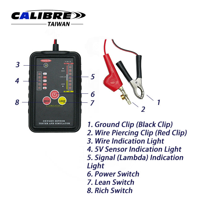
- Ground Clip (Black Clip)
- Wire Piercing Clip (Red Clip)
- Wire Indication Light
- 5V Sensor Indication Light
- Signal (Lambda) Indication Light
- Power Switch
- Lean Switch
- Rich Switch
1. Before The Test
1.1 Set Up Oxygen Sensor Type
CAUTION: To avoid the health hazard and damaging of device and wire, please connecting the tester with the vehicle before starting the engine, and after the exhaust system has cooled down. Please also keep away from parts that will generate high temperature or parts are in motion. This device can test and simulate 3 popular oxygen sensors. Please select the correct sensor type to obtain a correct testing result during the testing of oxygen sensor.
1.1.1 The pre-set sensor type is 1V Zirconia and 1V Titanium oxygen sensor when the power is just switched on.
1.1.2 Press and hold "RICH" switch, then press "Power ![]() "switch to switch on the power, the "Sensor Indication Light
"switch to switch on the power, the "Sensor Indication Light ![]() " will light up. This means the tester is ready for 5V Titanium oxygen sensor testing and simulating.
" will light up. This means the tester is ready for 5V Titanium oxygen sensor testing and simulating.
Note: User must switches off the power before change the sensor type.
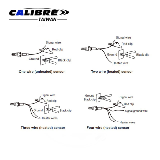
1.2 Connecting The Oxygen Sensor
1.2.1 Connecting the red clip to the signal wire.
1.2.2 Connecting the black clip to the ground, or negative polarity of the vehicle battery.
1.2.3 Read the "Signal Indication Light" and the "Wire Indication Light".
CAUTION: There is no standard color for oxygen sensor wires. Please read the datasheet to identify the wire.

2. Identify The Wire
By connecting the tester with the sensor wires, Indication Light will indicate the type of connected wire. (For most vehicles, user needs to start the engine to get a correct reading)

3. Test The Oxygen Sensor
3.1 Connecting The Tester With The Oxygen Sensor
Runt the engine at 1500 - 2000RPM for 3 minutes, this will make sure the engine and the oxygen sensor working in the normal operating temperature. For the connection, if the tester is connecting with a good oxygen sensor, the "Signal Indication Light" will start flowing up and down. Once the "Signal Indication Light" starts to flow, please ignore the flashing of "Wire Indication Light".
3.2 Testing The Oxygen Sensor For Pre-Catalytic Converter On Vehicle
(Flowing Fast)
The "Signal Indication Light" will flow lean to rich repeatedly when the tester is connecting with a normal oxygen sensor. The indication will repeat the flow continuously, and it will be at least 8 times within 10 seconds. If there is any error of oxygen sensor or the ECU, the indication light will not flow. The error condition will depend on the location of the indication light. CAUTION: If only two of the top indication lights is flashing on the "Signal Indication Light" when user testing with the 1V Zirconia and 1V Titanium mode, it means that the connected sensor is 5V Titanium. Please switch off the power and switch the mode to 5V Titanium. If the indication light starts to flow, it means the sensor is 5V Titanium.
3.3 Testing The Oxygen Sensor For Post-Catalytic Converter On Vehicle
(Flowing Slow Or Approaching To One Point)
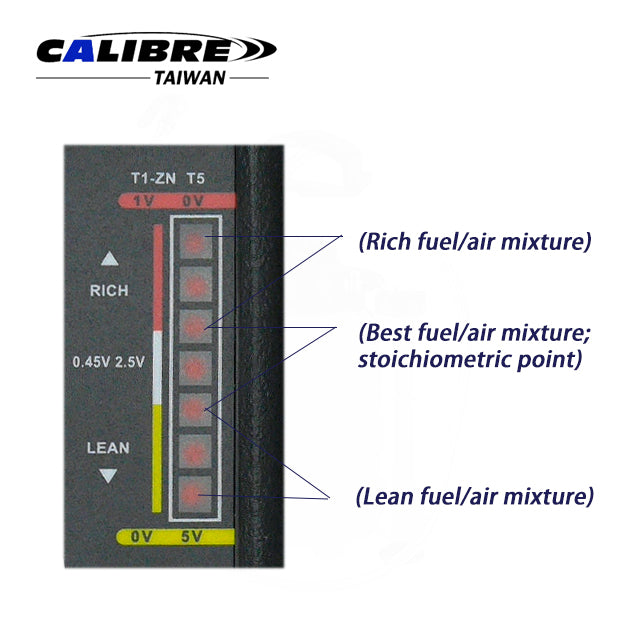
Note: Please make sure the oxygen sensor for pre-catalytic converter is working properly before testing the oxygen sensor on post-catalytic converter. The signal should be stable when user is testing a good oxygen sensor with a post- catalytic converter. The indication should be very close to 0.45V during the testing of good 1V Zirconia and 1V Titanium. For 5V Titanium, it will be around 2.5V. If the indication light is flowing, the oxygen sensor or the circuit may be damaged.
3.4 Testing The Oxygen Sensor Off Vehicle (Zirconia Type Only)
3.4.1 Remove the oxygen sensor from the vehicle.
3.4.2 Connecting the sensor with the tester.
3.4.3 Applying the flame of propane torch to the sensor. The first or second indication light should light up (0.8V or greater) as the oxygen sensor is heated by the flame, and the oxygen around the sensor has combusted. If not, the oxygen sensor may be damaged.
3.4.4 Turn off the propane torch, and the sensor will detect the oxygen in the environment, and so the indication light should drop to bottom (0.2V or smaller, the last two light).
CAUTION: For this test, user needs to use propane torch to heat up the sensor and burn the oxygen around the sensor. The temperature will be high. To avoid the hazard, please using the insulating tools to hold the sensor, and wear the protecting mask, glove, clothes.

3.5 Description Of Signal (Lambda) Indication Light

4. Oxygen Sensor Simulation

NOTE: To prevent the damaging of engine and converter, the simulating signal will only last for 4 seconds. User can switch between "RICH" and "LEAN" signal any time by pressing the button
By pressing the "RICH" button, the tester will simulate the rich fuel mixture signal to the ECU. If all parts of the vehicle are working well, the engine shall slow down, and for "LEAN" signal, the engine shall increase the rotation. The simulation will introduce different mixture signal to the system, and user can find out the possible problem by observing the response of the vehicle.
Note: For some the vehicle, it is possible obtain a fault code from the code reader because the simulating signal is different from its system.
INFORMATION
1. How It Work
Oxygen sensor is the key senor for the emission control system of the vehicle. By the feedback signal from the sensor the EUC. The vehicle is able to adjust the amount of injecting fuel. And so reduce the pollutants and fuel consumption.


If the oxygen concentration within the exhaust gases is too high, it is "lean mixture". During this condition, the combustion will not stable, speed will decrease, and temperature will increase, which will generate more nitrogen oxide. In worst case, it may damage the engine.
If the oxygen concentration within the exhaust gases is too low, it is "rich mixture". During this condition, the engine has more power, but the combustion is not completely done, and so more carbon monoxide and hydrocarbon will be generate which will waste the fuel.
2. Oxygen Sensor Type
• ZIRCONIA
Most popular oxygen sensor, it's based on Zirconium Dioxide. It will generate its own voltage. There two versions for this sensor; without heater (single wire), and with heater (2 - 4 wires). The working temperature is around 315°C (599°F), but the best performance is about 425°C (797°F). The output voltage signal will be 0.45V when it detects the best fuel and air mixture. During the testing, if the sensor is working well, the signal indication shall flow from low to high at least 8 times within 10 seconds.
• TITANIUM
It's based on Titanium dioxide. Depending on the design, it will need 1V or 5V power supply. This type of sensor is always with heater. The working temperature is between 426°C ~ 500°C (799°F ~ 932°F). For 1V, the output signal for lean to rich is OV ~ 1V, and the best mixture will be 0.5V. For 5V, it will generally reversed, the output signal for lean to rich is 5V-OV, and 2.5 for the best mixture. During the testing, if the sensor is working well, the signal indication shall flow from low to high at least 8 times within 10 seconds.
• WIDE BAND SINGLE CELL
To test this kind of sensor, user needs to disconnect the signal wire from the vehicle, but remain the heater wire connected. This is to prevent the interfering from the circuitry. Rest of the procedure is same as Zirconia. An alternative testing method will be off vehicle.
• WIDE BAND DUAL CELL
Bosch LSU4 series will be a good example for this kind of sensor. It is made by two Zirconia cells, one is a conventional oxygen sensor (reference cell), and another one is the oxygen pump. A good sensor will output a steady signal near 0.45V when user measures the output signal from the reference cell.
BATTERY REPLACEMENT

Battery: 9V, 6F22
Low Power Indication: Low battery indication light" will light up when battery power is not enough. Please change the battery.
WARNING: For safety purpose, please make sure the tester has completely disconnected with any other circuit before replacing the battery.
Couldn't load pickup availability
We are also good at
-

New Arrival
Discover top-rated automotive tools and mechanics tools at Projen Tools. The best...
-

Automotive Tools
high-quality auto repair tools with competitive factory-direct pricing. Custom branding available. Your...
-
General Tools
Auto tools, specifically general tools, are essential for performing a wide range...