


Projen Taiwan - Auto Tools, Hand Tools manufacturer
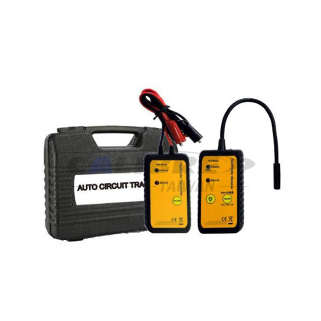
CAW0001 TAIWAN CALIBRE Auto Circuit Tracer
CAW0001 TAIWAN CALIBRE Auto Circuit Tracer
Circuit tester for cars
Circuit tester for cars helps diagnose short or open in vehicle wiring. Power on using the 9V battery. Use the green LED to identify open circuits and the red LED for shorts. Adjust sensitivity to low, medium, or high for accurate testing within 6–42V DC systems.Manual Download Here
Feature:
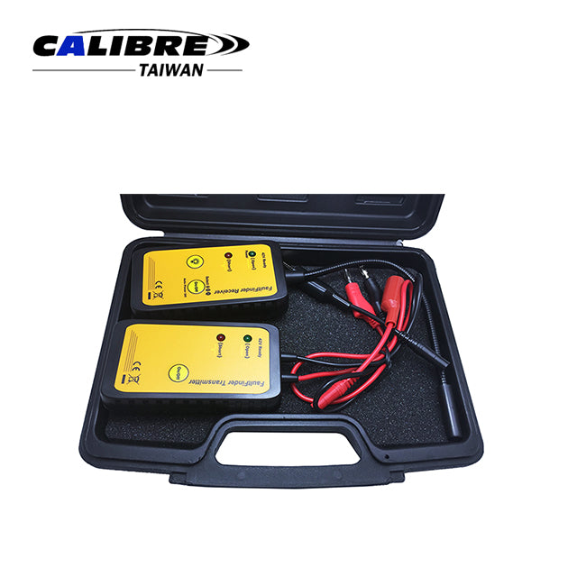
- Easy carry and operation equipment for car maintenance.
- For searching and diagnosing the short/open circuit of vehicles circuit connection.
- To identify the wire connection from whole vehicle’s circuit connection.
Application:
- Apply to 6~42V DC only
- Power source: 9V battery
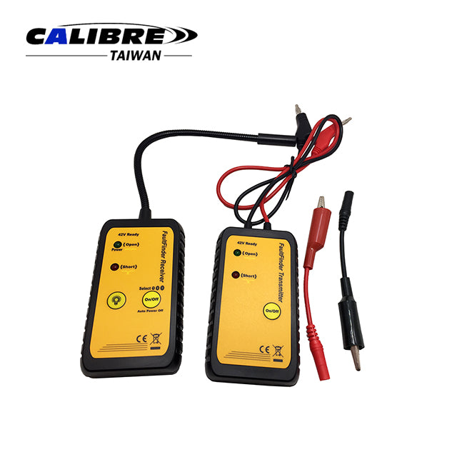
Indicators:
- Green LED for power On and Open circuits.
- Red LED for short circuits.
- Sensitivity: Three user selectable sensitivity levels. (Low, Medium and High)
Packaging:
- 1Set/Blow Mould Case
- 10Set/6/7kgs/1.2’
CAUTION BEFORE OPERATION
- Apply to DC voltage only.
- DC voltage must equal or under 42V.
- Do not connect with AC voltage.
- Do not connect with ignition circuit / system.
- Do not connect with pulse sensitive circuit like air bag, electronic control modules, etc.
- Please read the vehicle’s service manual before any operation.
- Please switch on the transmitter before connect with any circuit.
- Do not switch off the transmitter until disconnect with all circuit.
OPERATION
3.1 How to use the probe:

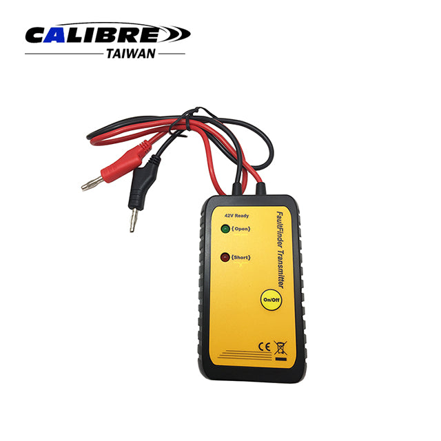
3.2 How to use the transmitter:
- Switch on the power by pressing “On/Off” button. If the circuit is “open”, green LED will flash. If the circuit is “short”, red LED will flash.
CAUTION:
The transmitter MUST be switched on before connecting with the vehicle’s circuit.
The power MUST switch off after disconnecting with the vehicle’s circuit. If not do
so, the fuse may be burned off when tester is connected with a shorted circuit.
3.3 How to use the receiver:
- Short press the “On/Off” button to switch on the power. Long press the “On/Off” button to change the sensitivity.
- The green LED “OPEN” indicator of the receiver will stay light (not flashing) when power is on.
- The green LED will start flashing when receiver senses the signal from the transmitter.
- The sensitivity will be on the weakest stage when the power is switched on. Long press the "On/Off" button until the buzzer buzzing twice and LED flashing twice. It indicates the sensitivity is on medium stage. Long press the “On/Off” button again until the buzzer buzzing three times and LED flashing three times. It indicates the sensitivity is on the strongest stage. The sensitivity will be rotated when user repeats above operation.
- Switch on the power, then press “
 ” to switch on the illumination.
 -
Green LED will keep flashing when receiver traces an “open”. Red LED will keep flashing when receiver traces a “short”.
-
Receiver power will switch off automatically after 25 seconds.
3.4 How to connect with the fuse socket:

3.5 How to trace “short”:
- Switch on the power, set the sensitivity to low.
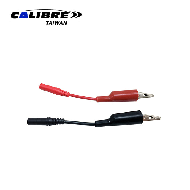
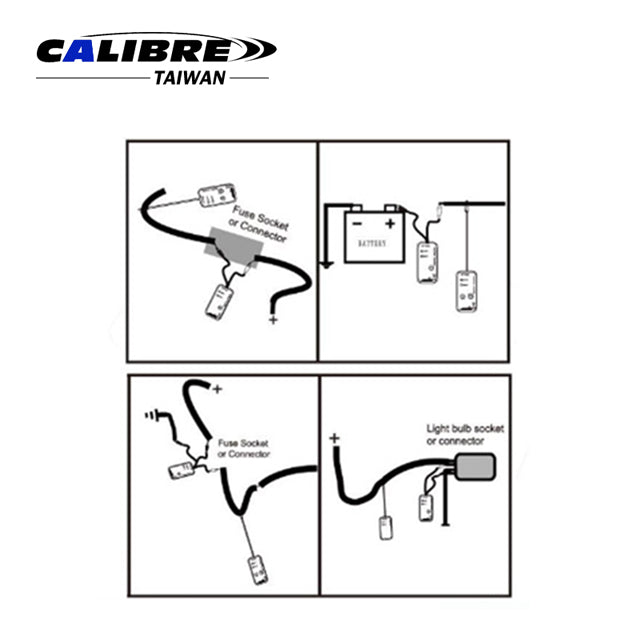
- Connect the two wires with the fuse socket; or connect the black wire to the (+) positive of the battery, and connect red wire to the other terminal which is connected with the system (Please refer to CONNECTION REFFERENCE Fig. A and Fig. B). If circuit is short, red LED will flash.
- If it is difficult to find the “short”, increase the sensitivity, and repeat procedure 2. Base on theconnection on Fig. A and Fig. B, if the circuit is under short condition, receiver will sense “short”, red LED will flash, and buzzer will buzz.
3.6 How to trace “open”:
- Switch on the power, set the sensitivity to low.
- Connect the two wires with the fuse socket; or connect the black wire to the (+) positive of the battery, and connect the red wire to the other terminal which is connecting with the system (Please refer to CONNECTION REFFERENCE Fig. A and Fig. B). If the circuit is open or normal, green LED on the transmitter will keep flashing.
-
Move the receiver alone the circuit slowly. If the circuit connecting with the transmitter is normal, the green LED on the receiver will keep flashing all the way, and the buzzer will keep buzzing.If any “OPEN” appears on the circuit, the green LED of the receiver will stop flashing near the “OPEN” position.
- If it is difficult to find the “open”, increase the sensitivity, and repeat procedure 3. Base on the connection of Fig. A, Fig. B, fig. C, and Fig. D, if the circuit is open or if the wire is the one user tracing, green LED will keep flashing and buzzer will keep buzzing.
3.7 How to trace wire:
- Same operation as 3.5 and 3.6. Alone the wire, user shall see the LED flashing and buzzer buzzing. If the buzzing and flashing frequency become slower, that means the receiver is away from the wire currently tracing. If no buzzing and flashing, that may mean signal been insulated or receiver is too far away from the signal. Please try with higher sensitivity.
3.8 How to identify wire:
- Same operation as 3.5 and 3.6. The wire with the signal shall have buzzing and flashing
when user move the receiver up on it. If it is a bundle of wires which have been tight together, user may need to separate them. Otherwise, due to the cross signal, other wire may receive weaker signal as well. If that is the case, the wire with the strongest buzzing volume, fastest buzzing and flashing frequency is the one which connected with the transmitter.
3.9 Connection reference:


3.10 Tracing multiple loads
- When user tracing with multiple loads (refer Fig E ), it is better to disconnect all the other un-needed loads. This is because the signal from the transmitter will flow alone the whole circuit, if there are too many loads; base on the circuit layout and loading circuit, it may reduce the signal strength, which will make it harder for the receiver to pick the signal.
- Moreover, all the circuit connect with the transmitter has the chance to pick the signal from the transmitter; these signal may be weak, but still been picked up by the receiver.
- Consequently, the least loads user is tracing, the easier to get the accurate result.

3.11 When to change battery:
Both red and green LED will flash then power off automatically if the battery is low.
MAINTENANCE
WARNING! DO NOT attempt to repair or service the auto circuit tracer unless you are
qualified to do so. To avoid damaging the instrument, do not get water inside the case.
- Periodically wipe the case with a damp cloth and mild detergent. Do not use solvents.
- Turn the sender and receiver off when not in use and remove the batteries if stored
for a long period of time. - Do not store in a place of high humidity or high temperature.
- To replace the batteries on either the sender or the receiver, simply open the rear of the unit battery cover and replace the battery with a 9V.
Couldn't load pickup availability
We are also good at
-
New Arrival
Discover top-rated automotive tools and mechanics tools at Projen Tools. The best...
-

Automotive Tools
high-quality auto repair tools with competitive factory-direct pricing. Custom branding available. Your...
-
General Tools
Auto tools, specifically general tools, are essential for performing a wide range...